Heads Up Displays with Holographic Smart Glass
Heads up displays with holographic smart glass show data superimposed onto the user’s field of view, reducing road fatalities caused by driver distraction


Approximately 3,000 people are killed each year in car accidents in the US alone due to driver distraction. This accounts for nearly 8% of all fatal road collisions in the US.
Common distractions include looking at your GPS, using your phone or changing radio stations.
So the question is:-
How can we provide critical information to drivers without distracting them?
Conventional methods have involved analogue dashboards, where the driver has to look down from the road view.
Even worse, more recent digital dashboards require you to navigate a touch screen to adjust basic controls (when a mechanical rotary dial is quicker and safer).
If only we could show information without requiring the driver to look away from the road.
This technology exists, of course, and we call it a ‘Heads Up Display.’
Heads-up displays project real-time information onto transparent surfaces, superimposing it just ahead of the vehicle and within the user’s line of sight.

This minimizes the time that the driver needs to refocus between viewing the information and the road ahead, thus reducing driver distraction.
The diagram below illustrates several projection distances (Virtual Image Distance, VID) and various horizontal viewing areas (Field of View, FOV):

The concept of ‘heads up, eyes forward’ is important in automobiles, but is also useful in other applications (some real, some futuristic), such as:

Heads up displays which pioneered in aircraft in the 1940s, and later appeared in passenger vehicles in the 1950s, were based on cathode rays tubes (CRTs), mirrors and lenses.
Unfortunately, these devices are heavy and take up a lot of space.
Digital heads up displays overcome the challenges of older ‘analogue’ HUDs and are either 2-dimensional or 3-dimensional.
These displays project onto a flat surface and currently use liquid crystal devices (LCDs), organic light-emitting devices (OLEDs), microLEDs, or DLP projectors.
Below you will find two such implementations:-

In general, 2-dimensional heads up displays offer good image quality and competitive pricing, but crucially they do not show depth in the image.
Depth allows highlighting areas on the road ahead which may present danger or require special attention, in a way that is natural to human vision.
Some stereoscopic 2-dimensional heads up displays attempt to create a 3-dimensional image by showing different images to each eye. This is known as the parallax effect.
Unfortunately, this can result in discomfort and nausea due to the difference in distances between the virtual object and the eye.
There are several 3-dimensional heads up display technologies competing in this space, including:-
This article will focus only on holographics as it is directly relevant to smart glass.
First, let’s look at some basic concepts regarding light that will help us to understand this topic.
We can model light in different ways:-
Geometric optics: | Modeling light as rays to calculate their angles of incidence and reflection |
Wave optics: | Modeling light as waves, from which we describe phenomena such as diffraction and interference |
Quantum optics: | Modeling light as discrete packets called photons, from which we understand concepts such as the photovoltaic effect (solar cells) |
These ‘paradigms’ explain how light interacts with the world and represent three different levels of abstraction.
As an analogy, we might view a building as:-
Wave optics is the best model for describing holographics, since it deals with diffraction and interference.
The diagram below compares the ways in which light can interact with matter, namely through reflection, absorption, refraction, scattering and diffraction.
In diffraction, what we see is light encountering a slit in an opaque slide, and ‘expanding out’ through the slit into multiple directions to form a semicircular wavefront.

When light interacts with the edge of the slit, it excites the material’s electrons, which pull the light away from its straight-line path.
The slit affects only the parts of the light wave closest to it. In essence, the light couples to the edge of the slit and travels as a surface wave, which changes its trajectory.
We think of light as bending around a corner by ‘sliding along’ the edge surface of the slit.
If a light wave bends around an object (as above), the wavefronts interact with each other.
This is interference and results in brighter and darker vertical regions appearing on a card placed opposite the slits.
You might remember this from your physics classes in secondary school.

We need to understand diffraction and interference in order to understand holography.
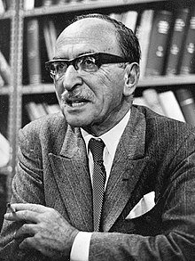
Holography was invented and coined by Dennis Gabor in 1948, who managed to add depth to the traditional 2-dimensional photograph.
It was not until the 1960s though, with the invention of the laser, that holography made advances. The precise, powerful and coherent light produced by the laser enabled the creation of holograms.
Gabor won the Nobel Prize in Physics in 1971 for his “invention and development of the holographic method”.
A hologram is a 2-dimensional or 3-dimensional image recorded on photosensitive film by a coherent light source (typically a laser).
The word stems from the Greek words:-
Hologram therefore translates as ‘whole message’.

We find the following examples of 2-dimensional holograms which reduce counterfeiting and forgery :-

Holograms capture not only the intensity (magnitude) of light, but also its ‘phase’ (‘timing’).
Holography is best described using wave optics (diffraction and interference), whereas photography is described using geometric optics (where light is modeled as straight-line rays).
Let’s look further at how photographs compare to holograms:-

Photographs are recorded using sunlight which is non-polarised or random in nature, whereas holograms need coherent light (typically a laser).
In creating a hologram, laser light is scattered from a 3-dimensional object onto a photosensitive plate and coincides with a reference beam coming from the same laser.

We can consider each point on the object as a light source, constituting the ‘object beam’, which illuminates the photosensitive plate.
Each light wave in the object beam travels a slightly different path from each point on the object to the photosensitive plate, arriving at minutely different times.
These differences are captured in the phase of light and stored as depth.
When the ‘object beam’ and the ‘reference beam’ reach the plate, they interfere and create a pattern of peaks and troughs, which are stored as variations in the refractive index of the plate.
A hologram thus effectively stores the optical distance that each photon of light has traveled.
If you look at the hologram with sunlight, the pattern will seem like a blurry image, because the object has been ‘encoded’ into the interference pattern.
We just cannot see it yet.
In reconstructing the hologram, we need to shine the same laser light (a ‘reconstruction beam’) onto the plate, which recreates a virtual image of the original object through diffraction.

Why diffraction?
Remember how light diffracted (bent) through the slit? It did that because it encountered a material with a different refractive index.
The refractive index of a material measures how much light is ‘slowed down’ as it interacts with it.
Think of how a person is ‘slowed down’ when they walk through a swimming pool. The same thing happens to light when it encounters a material of different refractive index.
In reconstructing the hologram, the ‘reconstruction beam’ encounters a plate with minute peaks and troughs of different refractive index, which causes light to diffract.
This diffraction then produces interference (just as with the slit above).
However, this time the interference results in a 3-dimensional virtual image of the original object, since that is the information that was encoded into the hologram.
What we have seen so far are static holograms of existing objects, recorded and then recreated by laser light. These are sometimes called ‘analogue holograms’.
Automotive heads up displays however need dynamically-generated content to show real time driver information, and this is where Computer-Generated Holography (CGH) comes in.
Whereas standard lenses and prisms refract light, a HOE diffracts light, generating an interference pattern in the same way that we would see with a static hologram.
Devices which implement this are called Holographic Optical Elements (HOEs), components that reproduce holographic images generated by a computer.
One example of such a HOE is a diffraction grating which is ‘burned’ onto the holographic film by the laser during the recording of the hologram.

Some of the most prominent manufacturers of holographic optical elements are listed below, in alphabetical order:-
Our definition of smart glass is broad:-
‘Any glazing material having surface coatings, internal structures or embedded circuits that influence the optical, electrical, thermal or mechanical properties of glass’.
Holographic smart glass perfectly fits within our definition.
Manufacturers often laminate holographic films between two sheets of glass (or plastic) to act as the medium that displays holographic images.
The driver’s field of view displays a 3D image containing critical road traffic and diagnostic information.
Holographic films allow for augmented-reality heads up displays (AR-HUDs), which redirect light more efficiently towards the driver, and at low power levels.
AR-HUDs can create larger images while taking up less space in the vehicle.
One example of an AR-HUD is in the Mercedes-Benz S-Class model (2021). You can find a video below.
The Heads Up Display (HUD) market outlook is strong, estimated to climb from USD 4.5 Billion in 2024 to USD 63 Billion by 2036, implying a Compound Annual Growth Rate (CAGR) of 24%.
Reasons for this optimism include:-
This is still very much a nascent field, with active research in progress, so we look forward to seeing more advances in these technologies and applications in the near future.


